Fig. 1 - Solar Thruster Sailor
| POST & AUTHOR & Vision | RSS - Ring Skeleton Structure | LTH - Launcher Transport Head | EFO - Experimental Flying Object | RSC - Rotational Slingshot Catapult |
|
The Solar Thruster Sailor (STS) combines electric thrusters mounted on an Outer Ring with solar sail propulsion and a large payload area. If combined with an Inner Ring as a docking and payload station, the space craft can serve as a carrier for a satellite swarm or space craft fleet, a container ship or a space tug which is able to handle payload in itṀs center. Try this with a mast and boom based or heliogyro type solar sail :-) .
The following figures contain some German words because I used them in the patent-application at the German "Patentamt".
Main elements of fig 1 are thruster-ring "1" with double thruster units mounted on itṀs outer edge, solar sail and solar cells with carbon belts stretched within "2", carrying a (carbon) payload-platform in the middle "3". Thruster units 1.5 are for right - left- rotation around the pole. Thruster units 1.6 are for up - down rotation around the diameter.
Thruster units, parts 1.9 are at the same time brackets and tank units for xenon-gas. Parts 1.10 are jet tubes consisting of two thrusters with outlet to opposed directions.
The two splints of the bracket 1.9 run completely through the segment-pipes and are boltet onto them with counter nuts. The splints are also conductors for the electric power yielded from the solar-cells near the thruster-unit. Half-pipes (could be from metal) 1.9.2 enfold the segment pipes to give this joints some more strength since they have to resist heavy rotational forces.

The bracket for the unit is at the same time tank for xenon gas
As simple as it can get. If you have one plate with inbuilt screws and the other plate with holes there is not much work to do to mount the belt.
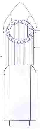
Fig. 4.cLauncher Transport Head (LTH) |
Fig. 4.aone layer LTH from above |
Fig. 4.bmultiple layer LTH from above |
|
 If the upper stage of the launcher has a diameter of 4 m and the pipe segments a diameter of about 6 cm, it is possible to transport up to 200 pipes. Given a length of about 15 m per segment youṀll get a perimeter of 3000 m from one layer. The compressed mass volume of this layer is about 0,6 cubicmeter of lightweight material. Not a weight to worry about for a big solar sailor-structure.
|
 A multilayer LTH could transport pipes for very large ring structures. |
to the next Fig.5 -
| POST & AUTHOR & Vision | RSS - Ring Skeleton Structure | LTH - Launcher Transport Head | EFO - Experimental Flying Object | RSC - Rotational Slingshot Catapult |
|